trane thermostat wiring guide
Welcome to your comprehensive guide to Trane thermostat wiring! This resource provides the essential information and steps needed to confidently handle your Trane thermostat wiring projects. Whether replacing an old unit or installing a new smart thermostat, you’ll find the knowledge you need here.
Trane thermostats are integral components of home comfort systems, offering precise climate control and energy efficiency. Understanding their wiring is crucial for proper installation, replacement, and troubleshooting. Trane offers a variety of thermostats, from basic models to advanced smart thermostats, each with unique wiring configurations.
This guide aims to demystify the wiring process, providing clear instructions and safety precautions. Whether you’re a homeowner looking to upgrade your thermostat or a technician working on a Trane system, this resource will equip you with the knowledge to tackle any wiring task.
Trane thermostats often utilize specific wiring conventions, such as using the “B” terminal as a common wire, which differs from some other brands. Recognizing these nuances is essential for successful wiring. Smart thermostats, like Nest, can often be compatible with Trane systems, sometimes requiring a conventional thermostat interface board for proper signal conversion. This board adapts the signals to 24VAC, ensuring seamless communication between the thermostat and the HVAC unit.
With the right tools and understanding, wiring a Trane thermostat can be a straightforward process, enhancing your home’s comfort and energy savings.
Identifying Your Trane Thermostat Model
Before embarking on any wiring project, accurately identifying your Trane thermostat model is paramount. Different models have varying wiring configurations, terminal designations, and compatibility requirements. Locating the model number ensures you consult the correct wiring diagrams and instructions, preventing potential damage to your system.
The model number is typically found on a label affixed to the thermostat’s back or side. This often requires removing the thermostat from its base plate. Carefully detach the thermostat, being mindful of any connected wires. Once removed, examine the back panel for a sticker containing the model number, serial number, and other relevant information.

Common Trane thermostat models include the BAYSTAT series, such as BAYSTAT239 or BAYSES008B, and the ZSM-11-1 used with the ZN523 Zone Controller. Each model has a specific wiring configuration. Online resources and Trane’s official documentation provide detailed wiring diagrams for each model. Accurate identification allows for precise wiring according to the manufacturer’s specifications.
Knowing your thermostat model also helps determine compatibility with smart thermostats or interface boards. This ensures that any upgrades or replacements integrate seamlessly with your existing HVAC system.

Essential Tools and Materials for Wiring
Proper preparation is key to a successful thermostat wiring project. Gathering the right tools and materials beforehand ensures a smooth and safe installation process. This prevents unnecessary delays and minimizes the risk of errors that could damage your thermostat or HVAC system.
First, you’ll need a set of screwdrivers, including both Phillips head and flathead types, in various sizes to accommodate different terminal screws. A wire stripper is essential for safely removing insulation from the thermostat wires without damaging the conductors. A pair of pliers is useful for bending and manipulating wires, ensuring secure connections.
A multimeter is crucial for testing voltage and continuity, verifying that the wiring is correct and that the system is functioning as expected. Ensure you have enough 18-gauge color-coded thermostat wire to reach from the thermostat to the HVAC unit. A wire connector can be used to connect the wires.
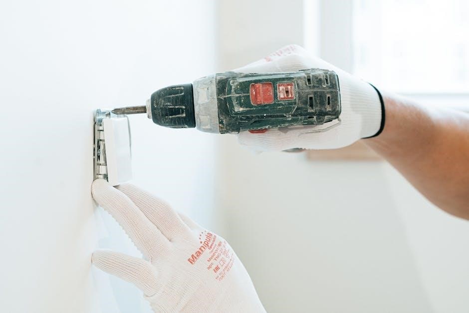
Safety glasses and gloves are necessary to protect your eyes and hands during the wiring process. A flashlight or headlamp provides adequate lighting, especially when working in dimly lit areas. Finally, have a digital camera or smartphone readily available to take pictures of the existing wiring configuration before making any changes. This serves as a valuable reference during reassembly.
Safety Precautions Before Wiring
Prioritizing safety is paramount before commencing any thermostat wiring work. Electrical systems can be hazardous, and taking the necessary precautions minimizes the risk of injury or damage to your equipment. Neglecting safety measures can lead to electric shock, short circuits, or even fire hazards.
The first and most crucial step is to always turn off the power to your HVAC system at the circuit breaker. Confirm that the power is off by using a non-contact voltage tester on the thermostat wires. Never assume the power is off just because you flipped the breaker; double-check to be certain.

Wear safety glasses to protect your eyes from any debris or accidental sparks. Insulated gloves provide an additional layer of protection against electrical shock. Avoid working in damp or wet conditions, as water increases the risk of electrical hazards. If you are uncomfortable working with electrical wiring, it is best to consult a qualified HVAC technician.
Carefully inspect the existing wiring for any signs of damage, such as frayed insulation or corroded wires. Replace any damaged wires before proceeding with the installation. Keep children and pets away from the work area to prevent accidents. Finally, take your time and avoid rushing the wiring process. Rushing can lead to mistakes and potentially dangerous situations.
Understanding Thermostat Wiring Terminals
Before you begin wiring your Trane thermostat, it’s crucial to understand the function of each terminal. Thermostat wiring uses standardized color codes, but it’s always best to verify the wiring configuration with your system’s documentation. Correctly identifying the terminals ensures proper operation and prevents damage to your HVAC system.
Here’s a breakdown of common thermostat wiring terminals:
- R (Red): Power supply, typically 24VAC. May be labeled Rc (cooling) or Rh (heating) in dual-transformer systems.
- W (White): Heat. Activates the heating system. Could be W1 for primary heat or W2 for auxiliary/emergency heat.
- Y (Yellow): Cooling. Activates the air conditioning system. Usually labeled Y1 for the primary compressor and Y2 for a second compressor stage.
- G (Green): Fan. Controls the blower fan, circulating air throughout your home.
- C (Common/Blue): Provides a return path for the 24VAC power, essential for many modern thermostats.
- B (Blue): Often used as Common (C) in Trane systems.
- X: Emergency heat (Trane specific)
Note that wire colors may not always match the terminal labels due to variations in installation practices. Always refer to your thermostat and HVAC system manuals to confirm the correct wiring configuration. Using a multimeter can help verify voltage and confirm the function of each wire.
Common Trane Thermostat Wiring Configurations
Trane thermostats are used in a variety of HVAC systems, leading to several common wiring configurations. Understanding these configurations is essential for correct installation and optimal performance. Here are some typical setups you might encounter:
- Standard Heating and Cooling System: This basic setup usually involves R, W, Y, G, and C wires. The R wire provides power, W activates the heating, Y controls the cooling, G operates the fan, and C provides the common connection.
- Heat Pump System: Heat pumps require additional wiring for reversing valve control. Common terminals include R, W, Y, G, C, and O/B. The O/B terminal controls the reversing valve, switching between heating and cooling modes.
- Heat Pump with Auxiliary Heat: In colder climates, heat pumps often include auxiliary or emergency heat. This configuration adds a W2 terminal for the auxiliary heat source, providing supplemental heating when the heat pump cannot meet the demand.
- Trane-Specific Systems: Some Trane systems use unique wiring configurations, such as the B terminal as Common and an X terminal for emergency heat; Always consult the Trane documentation for these systems.
When replacing a thermostat, carefully note the existing wiring configuration before disconnecting any wires. Taking pictures or making a diagram will help ensure accurate reconnection.
Wiring a Basic Trane Thermostat
Wiring a basic Trane thermostat involves connecting several wires to their corresponding terminals. These wires typically include the R (power), W (heating), Y (cooling), G (fan), and sometimes a C (common) wire. Follow these steps for a successful installation:
- Turn off the power: Before starting any wiring work, switch off the breaker that controls your HVAC system to avoid electrical shock.
- Remove the old thermostat: Carefully detach the old thermostat from its base, noting the wire connections; Label each wire if necessary.
- Connect the wires: Match the wires to the corresponding terminals on the new Trane thermostat. Typically, R goes to R, W to W, Y to Y, and G to G. If you have a C wire, connect it to the C terminal.
- Secure the thermostat: Attach the new thermostat base to the wall, ensuring it is level. Then, snap the thermostat unit onto the base.
- Restore power: Turn the breaker back on and test the thermostat to ensure it controls the heating, cooling, and fan functions correctly.
If your system lacks a C wire, you may need to install a C wire adapter or use a thermostat that doesn’t require one. Always consult the thermostat’s manual for specific instructions.
Wiring a Trane Thermostat with Heat Pump
Wiring a Trane thermostat with a heat pump system requires careful attention to ensure proper functionality. Heat pumps use a reversing valve to switch between heating and cooling modes, which adds complexity to the wiring. Here’s a guide:
- Identify the wires: Common wires include R (power), Y (compressor), G (fan), and a reversing valve wire, which can be O or B. Some systems may also have an auxiliary heat wire (W or Aux).
- Determine the reversing valve type: Heat pumps can be either O (energized in cooling) or B (energized in heating). Check your system’s documentation.
- Connect the wires: Connect R to R, Y to Y, and G to G. If the reversing valve is O, connect it to the O terminal on the thermostat. If it’s B, connect it to the B terminal. Connect the auxiliary heat wire (W or Aux) to the corresponding terminal.
- Configure the thermostat: Some thermostats require you to specify that you have a heat pump system and whether the reversing valve is O or B.
- Test the system: After wiring, test both heating and cooling modes to ensure the heat pump is functioning correctly.

If you encounter issues, consult your thermostat’s manual or a qualified HVAC technician.
Wiring a Trane Thermostat with Emergency Heat
Wiring a Trane thermostat with emergency heat involves connecting an additional wire to activate a backup heating source, typically electric resistance heat. This ensures warmth when the heat pump is unable to provide sufficient heating.
- Identify the W2 or Aux terminal: Locate the terminal on your thermostat labeled W2 or Aux, which is specifically for emergency heat.
- Connect the emergency heat wire: Run a wire from the W2/Aux terminal on the thermostat to the corresponding terminal on your HVAC system’s control board.
- Ensure proper configuration: Some thermostats require configuration to recognize the emergency heat function. Access the thermostat’s settings menu and enable the emergency heat option.
- Test the emergency heat: After wiring, test the emergency heat by manually activating it through the thermostat. Verify that the backup heating source engages and provides heat.
Important Considerations:
- Wire Gauge: Use the appropriate gauge wire to handle the electrical load of the emergency heat system. Consult the manufacturer’s specifications for guidance.
- Professional Assistance: If you are unfamiliar with electrical wiring or HVAC systems, seek assistance from a qualified technician to ensure safe and correct installation.
Connecting a C-Wire (Common Wire)
Connecting a C-wire, or common wire, provides a stable 24VAC power supply to your thermostat, which is essential for many modern thermostats, especially smart models. Without a C-wire, these thermostats might not function correctly or could draw power from other components, potentially causing issues.
Steps for Connecting a C-Wire:
- Identify the C Terminal: Locate the C terminal on both your thermostat and your HVAC system’s control board. It’s often blue.
- Run a New Wire: If you don’t have an existing C-wire, run a new wire from the C terminal on the HVAC system to the C terminal on the thermostat.
- Connect the Wires: Securely connect both ends of the C-wire to the designated terminals. Ensure the connections are tight.
- Power Cycle: Turn off the power to your HVAC system at the breaker before making any connections, and then restore it after wiring.
- Test the Thermostat: After connecting the C-wire, test the thermostat to ensure it powers on and functions correctly.
Troubleshooting Tips:
If your system doesn’t have a C terminal, you might need to install a C-wire adapter or a separate 24VAC transformer to provide the necessary power. Always consult the thermostat’s manual for specific instructions.
Replacing an Old Trane Thermostat with a New One
Replacing an old Trane thermostat with a new one can enhance your home’s comfort and energy efficiency. This process requires careful attention to wiring and configuration to ensure compatibility and proper functionality.
Steps for Replacing Your Thermostat:
- Turn Off Power: Always begin by turning off the power to your HVAC system at the circuit breaker to prevent electrical shock.
- Remove the Old Thermostat: Carefully detach the old thermostat from the wall. Note the existing wiring configuration, labeling each wire with tape.
- Install the New Mounting Plate: Mount the new thermostat’s base plate to the wall, ensuring it’s level.
- Connect the Wires: Connect the wires to the corresponding terminals on the new thermostat, matching the labels from the old thermostat.
- Attach the Thermostat: Secure the new thermostat to the base plate.
- Restore Power: Turn the power back on at the circuit breaker.
- Configure the New Thermostat: Follow the manufacturer’s instructions to configure the new thermostat, including setting the date, time, and desired temperature settings.
Important Considerations:
If you’re unsure about any step, consult a qualified HVAC technician. Ensure the new thermostat is compatible with your HVAC system for optimal performance.
Troubleshooting Common Wiring Issues
Encountering issues after wiring your Trane thermostat is not uncommon. This section provides guidance on troubleshooting typical problems.
Common Problems and Solutions:
- Thermostat Not Turning On: Ensure power is supplied to the HVAC system. Check the circuit breaker and thermostat batteries. Verify correct wiring connections.
- Incorrect Temperature Readings: Calibrate the thermostat if possible. Ensure the thermostat is not exposed to direct sunlight or drafts.
- HVAC System Not Responding: Double-check wiring connections. Confirm compatibility between the thermostat and HVAC system. Review the thermostat’s programming.
- Fan Running Continuously: Check the fan wiring. Ensure the fan setting is correct (Auto or On).
- Heating or Cooling Not Working: Verify the thermostat is set to the correct mode (Heat or Cool). Check wiring connections for the heating and cooling components.
- C-Wire Issues: If your system requires a C-wire and it’s not connected properly, it can cause various problems. Ensure it is securely connected to the appropriate terminal.
Additional Tips:
Consult the thermostat’s manual for specific troubleshooting steps. If problems persist, contact a qualified HVAC technician for professional assistance.
Smart Thermostat Compatibility with Trane Systems
Upgrading to a smart thermostat offers enhanced control and energy savings. However, ensuring compatibility with your Trane system is crucial for seamless integration.
Compatibility Considerations:
- Voltage Requirements: Confirm the smart thermostat’s voltage requirements match your Trane system (typically 24VAC).
- Wiring Compatibility: Check the availability of necessary terminals (R, W, Y, G, C) on both the thermostat and your Trane HVAC system.
- System Type: Determine if your Trane system is a conventional furnace/AC or a heat pump. Heat pump systems have unique wiring configurations.
- C-Wire Requirement: Many smart thermostats require a C-wire for continuous power. If your system lacks a C-wire, consider using a C-wire adapter or a thermostat that doesn’t require one.

Installation Tips:
- Carefully label existing wires before disconnecting them from your old thermostat.
- Consult the smart thermostat’s installation guide for Trane-specific wiring diagrams.
- If unsure, seek assistance from a qualified HVAC technician to ensure proper wiring and avoid damage to your system.
Benefits of Smart Thermostats:
- Remote control via smartphone or tablet.
- Programmable schedules for energy savings.
- Learning capabilities to adapt to your preferences.

Wiring a Trane Thermostat Interface Board
In some Trane systems, particularly older models, a thermostat interface board is required to connect a standard thermostat. This board acts as a translator, converting the thermostat’s signals into a format the Trane unit understands.
Understanding the Interface Board:
- The interface board typically has terminals for both the thermostat wires and the Trane system’s control wires.
- It often converts the thermostat’s 24VAC signals to a different voltage or signal type used by the Trane equipment.
Wiring Procedure:
- Identify Terminals: Carefully identify the terminals on both the thermostat and the interface board. Common labels include R, C, W, Y, G, and potentially others specific to Trane systems.
- Connect Thermostat Wires: Connect the corresponding thermostat wires to the appropriate terminals on the interface board.
- Connect Trane System Wires: Connect the Trane system’s control wires to the designated terminals on the interface board.
- Refer to Wiring Diagram: Always consult the wiring diagram provided with the interface board or the Trane system documentation.
- Double-Check Connections: Before powering on the system, double-check all connections for accuracy and tightness.

Important Notes:
- Incorrect wiring can damage the thermostat, the interface board, or the Trane system.
- If you are not comfortable working with electrical wiring, consult a qualified HVAC technician.
Final Checks and Testing After Wiring
After completing the thermostat wiring, performing thorough final checks and testing is crucial to ensure proper functionality and prevent potential issues. This meticulous process guarantees that your Trane system operates efficiently and safely.

Visual Inspection:
- Carefully inspect all wire connections at both the thermostat and the HVAC unit.
- Ensure wires are securely fastened to the terminals and that no bare wires are exposed.
- Verify that the thermostat is properly mounted and level on the wall.
Powering On:
- Turn on the power to the HVAC system at the circuit breaker.
- Observe the thermostat display to confirm it powers on correctly.
Testing Heating and Cooling:
- Set the thermostat to “Heat” mode and raise the temperature above the current room temperature. Verify that the heating system activates.
- Set the thermostat to “Cool” mode and lower the temperature below the current room temperature. Verify that the cooling system activates.
- Check the fan operation in both “Auto” and “On” modes.
Troubleshooting:
- If the system does not respond as expected, double-check the wiring connections against the wiring diagram.
- Consult the thermostat’s user manual or the Trane system documentation for troubleshooting tips.
- If you are unable to resolve the issue, contact a qualified HVAC technician for assistance.

